What MOPITT measures:
MOPITT is a nadir sounding instrument, which provides a horizontal resolution of 22 km, but introduces a number of challenges, such as the need for accurately characterizing the surface contribution to the signal. During operations, MOPITT scans across the satellite flight track +/- 26.1 deg in 13 secs.

Figure 1: MOPITT operates by sensing infrared radiation from either the thermal emission/absorption at 4.7 µm for CO profiles, or reflected sunlight at about 2.2-2.4 µm for CO and CH4 column measurements in daylight. The use of solar channels enhances the instrument sensitivity to the atmospheric boundary layer.
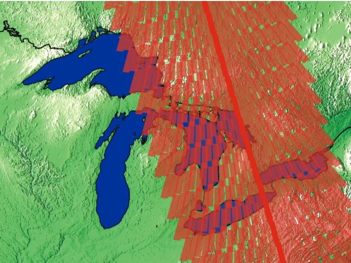
Figure 2: an example of a MOPITT scan pattern as it flies over Southern Ontario.
Correlation Radiometry:
MOPITT uses correlation radiometry for the detection of CO and CH4. Both pressure-modulated and length-modulated cells are employed for this, each with their own strengths.
The pressure modulated cells/radiometers (PMCs) operates by changing the cell gas pressure using a piston. The advantages of this are few moving parts and an increased instrument sensitivity to the upper troposphere, while the disadvantages include complex pressure and temperature cycles and a limit to the upper pressure.
The length modulated cells/radiometers (LMCs) operates by changing the gas path length by rotating a calcium fluoride disk in the vacuum cell, thus modulating the gas amount. The advantages of this are simple pressure, temperature, and time behaviour, and the pressures can be higher than the PMCs; however, the disadvantages include that the optical components are moving, leaving the possibility of potential system imbalances. The MOPITT mission is the first time LMCs are used in space.
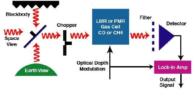
Figure 3: Signals pass through a cell containing the target gas, CO or CH4. The cell pressure or length is varied, which produces a modulation in cell opacity within the lines of the target gas, while the cell opacity at other frequencies remains constant.

Figure 4: PMC.

Figure 5: LMC.
Optical Channels:
MOPITT has eight channels laid out on 2 optical benches. Each of the eight channels is designed to measure a specific gas using either a LMC or a PMC.
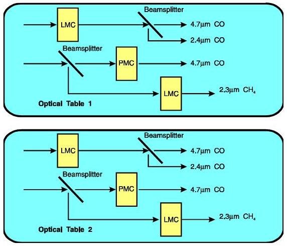
Figure 6: MOPITT optical channels.
| Channel # | Primary Gas | Modulator Type | Cell Pressure (mb) | Cell Temperature (K) | Cell Length (mm) | Spectral Band | Center Wavenumber (cm-1) |
|---|---|---|---|---|---|---|---|
| 1 | CO | LMC1 | 200 | 300 | 2-10 | CO thermal | 2166 (52) |
| 2 | CO | LMc1 | 200 | 300 | 2-10 | CO solar | 4285 (40) |
| 3 | CO | PMC1 | 50-100 | 300 | 10 | CO thermal | 2166 (52) |
| 4 | CH4 | LMC2 | 800 | 300 | 2-10 | CH4 solar | 4430 (140) |
| 5 | CO | LMC3 | 800 | 300 | 2-10 | CO thermal | 2166 (52) |
| 6 | CO | LMC3 | 800 | 300 | 2-10 | CO solar | 4285 (40) |
| 7 | CO | PMC2 | 25-50 | 300 | 10 | CO thermal | 2166 (52) |
| 8 | CH4 | LMC4 | 800 | 300 | 2-10 | CH4 solar | 4430 (140) |
Measurements:
The operation of the modulator cells leads to measurements made in two states. The signal from these two states is averaged and differenced. The average signals are low at the line of interest, providing information about background radiance and interfering signals. The difference signals have only significant response at the line of interest, providing information about the gas of interest. The pressure of the cells determines the portion of the pressure-broadened line wing that is sampled. Combining PMCs and LMCs with different pressures thus provides information about the vertical profile.

Figure 7: MOPITT high and low opacity signals generated by the two states of the PMC.
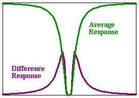
Figure 8: MOPITT average and difference signals generated from measurements of the two modulator cell states.
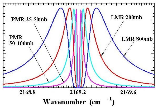
Figure 9: Pressure-broadened lines and the impact of operating pressure on them.
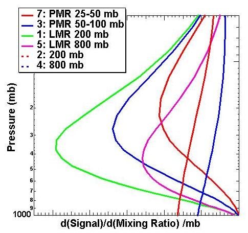
Figure 10: The weighting functions for the different cell pressures of the 6 CO channels.