The MOPITT (Measurements of Pollution In The Troposphere) instrument measures up welling radiation in three narrow infrared (IR) bands:
- 4.7 μm channels that have strong carbon monoxide (CO) absorption characteristics and are referred to as CO thermal channels because the dominant signals are from the thermal emission of the atmosphere and the Earth’s surface;
- 2.3 μm channels that have weak CO absorption and are referred to as CO solar channels due to the reflected sunlight being the dominant signal;
- 2.2 μm channels that have weak methane absorption for the band where reflected sunlight is the major signal source and are termed the methane solar channels.
The MOPITT instrument makes use of the principle of correlation spectroscopy whereby a cell of the gas to be measured is used as an optical filter in the infrared to measure the signal from the same gas in the atmosphere. The amount of gas in the instrument cell is modulated by varying either the cell's pressure, for a Pressure Modulated Cell (PMC), or its length, for a Length Modulated Cell (LMC). MOPITT utilizes an array of correlation radiometer channels such that the thermal channels (4.7 μm) are most sensitive to upper and mid-tropospheric CO and the solar channels (2.3 μm) are most sensitive to the total CO column. Major features of the electromagnetic energy received by the instrument are the absorptions and emissions by the atmospheric constituents at their distinctive spectral lines. For each measurement, a correlation gas modulator takes two samples by alternating the amount of the absorbing gas in the correlation cell between two states. Changes occur only in the target gas absorption lines. For the rest of the spectrum, including other contaminating gas absorption lines, the absorption is essentially unchanged. The difference of the two states leaves only the changes at the correlation gas absorption lines and eliminates other components because they are not modulated between the two samples.
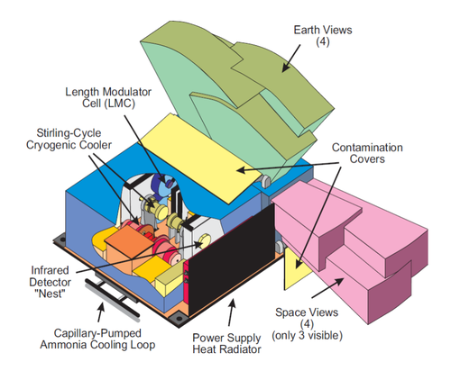
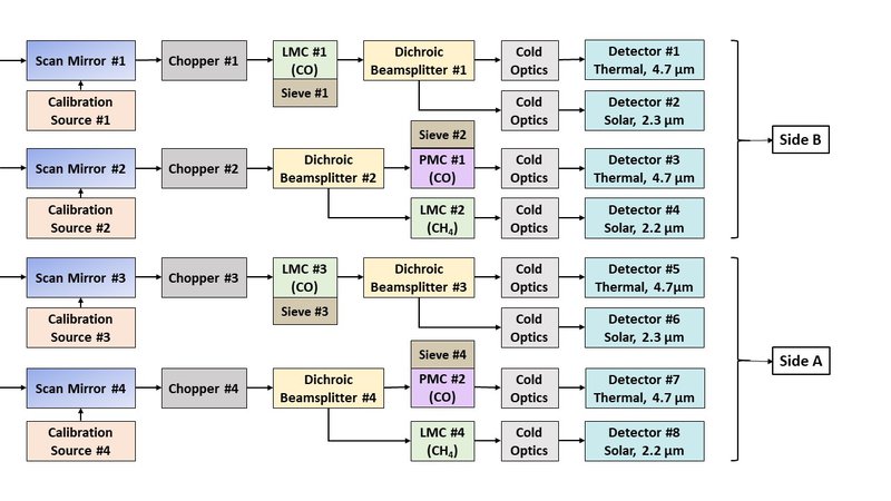
The MOPITT instrument layout can be seen in the figure below. This design achieves an optimal combination of LMCs and PMCs, thermal and solar channels, carbon monoxide and methane gases as well as allowing significant redundancy. It is comprised of 8 channels: channel 1 to 4 are referred to as side B and channels 5 to 8 are referred to as side A. Side A and side B, although not perfect duplicates, are redundant to each other in the sense that one side can perform approximately the same function as the other side with some performance degradation. The detectors for each side are cooled by two separate coolers.
Through application of the MOPITT retrieval algorithm to the calibrated radiance measurements, vertical profiles of CO concentration are obtained on a global basis at moderately high horizontal resolution (~22 km). Retrievals of methane have been unsuccessful because of problems with excessive noise from both instrumental and geophysical sources. MOPITT retrieved CO profiles are either analyzed directly or assimilated into models to study the chemistry and dynamics of CO (and other constituents) in the lower atmosphere. MOPITT retrievals of CO have been thoroughly validated in a variety of geographical settings.
The measurement of CO profiles has long been identified as being of primary importance in an effort to improve our understanding of the global system. This has been recognized by the EOS Science Steering Committee, which asserted that "[t]he fate of carbon monoxide, remotely detected from space, in conjunction with a few other critical meteorological and chemical parameters, is crucial to our understanding of the chemical reaction sequences that occur in the entire troposphere and govern most of the biogeochemical trace gases" (EOS, 1987). This view is supported by the World Meteorological Organization, which published the statement that the "[d]efinition of trends and distributions for tropospheric CO is essential. A satellite-borne CO sensor operating for extended periods could help enormously" (WMO, 1985).
More information about the concept and operation principles of MOPITT can be found at the NCAR MOPITT website.
References
Drummond J.R., Zou J., Nichitiu F., Kar J., Deschambaut R., Hackett J., (2010), A review of 9-year performance and operation of the MOPITT instrument, Advances in Space Research, 45 (6), pp 760-774, doi.org/10.1016/j.asr.2009.11.019